Weld Hole Detector for special applications
DTR540 / EMR-C
- Large field of detection and off-centered strip
- For detection of 1 or 2 holes
- Smart functions of receiver
- Easy setup and alignment
Présentation
Le récepteur DTR540 est un réseau de diodes linéaires. Associé à l’émetteur de lumière EMR-C (LED rouge) il est capable de détecter le trou de soudure prévu pour localiser la soudure liant 2 bandes.
Le récepteur se compose d’un objectif, d’un réseau de diodes linéaires et d’une unité de traitement protégés par un boîtier étanche en fonte d’aluminium. L’image de la cible est projetée sur le réseau de diodes. La sortie du récepteur DTR540 commute lorsqu'un trou est vu dans son champ de vision - avec l'émetteur de lumière EMR-C en arrière-plan.
DELTA propose deux modèles de détecteurs de trous de soudure pour des applications différenciées :
- DTS240/EMR-M : pour les applications standard, c’est-à-dire la déviation du trou doit être inférieure à 340 mm et l’émetteur EMR-M-400 doit être complètement masqué par la bande.
- DTR540/EMR-C : quand la position du trou varie beaucoup ou quand la bande est étroite et décentrée (remplacement de l’ancien modèle DTR340). Le DTR540/EMR-C convient également à des lignes équipées pour la détection de deux trous de soudure en même temps (remplacement de l’ancien modèle DTR522).
Caractéristiques
Le détecteur DTR540 a été conçu pour l’industrie lourde, avec son équerre de fixation orientable selon deux axes. Ainsi, il est possible de remplacer le capteur sans devoir l’orienter à nouveau.
Le capteur est ‘intelligent’ dans la mesure où il est capable de reconnaitre le trou de soudure selon sa taille et sa position. Le champ de vision peut être ajusté par l’opérateur en fonction de la distance d’installation.
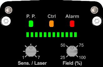
Le réglage du capteur est facilité par le panneau de contrôle comprenant :
- 3 LED indiquant l’état du capteur :
- P.P. est vert quand la sortie détection est activée (présence produit).
- Ctrl est orange quand la marge de détection est insuffisante.
- Alarm est rouge quand la sortie alarme est activée (T° interne trop élevée, défaut récepteur).
- Le bargraph (LED vert) affiche le champ de vision actif et la position du trou dans ce champ.
- Le potentiomètre ‘Field’ pour régler l’angle de détection.
- Le potentiomètre ‘Sens./Laser’ pour ajuster la sensibilité (combinaison de la taille, du filtre et du temps d’intégration). Un laser vert en forme de croix pour l’aide à l’alignement du récepteur regardant l’émetteur, s’allume : soit automatiquement à sa mise sous tension, soit en actionnant le potentiomètre de sensibilité (se coupe automatiquement 15 min après son allumage).
|
 |
Accessoires et Options
- Support de montage réglable pour émetteur EM•-C

- Coffret de raccordement pour connecter

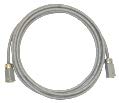
- Câble d’alimentation et E/S entre coffret de raccordement et DR•500 et
EM•-C, sous gaine de protection en acier, avec 2 connecteurs : 5 m, 8 m, 10 m ou 15 m
‹ Back to list

 USA
USA Deutsch
 English
 Español
 Français
 Italiano
 Pусский
 中国
中国